PROJ.

Nak

A 3D-printed, 18-DOF, RC-controllable hexapod

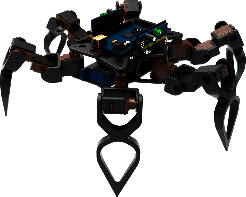
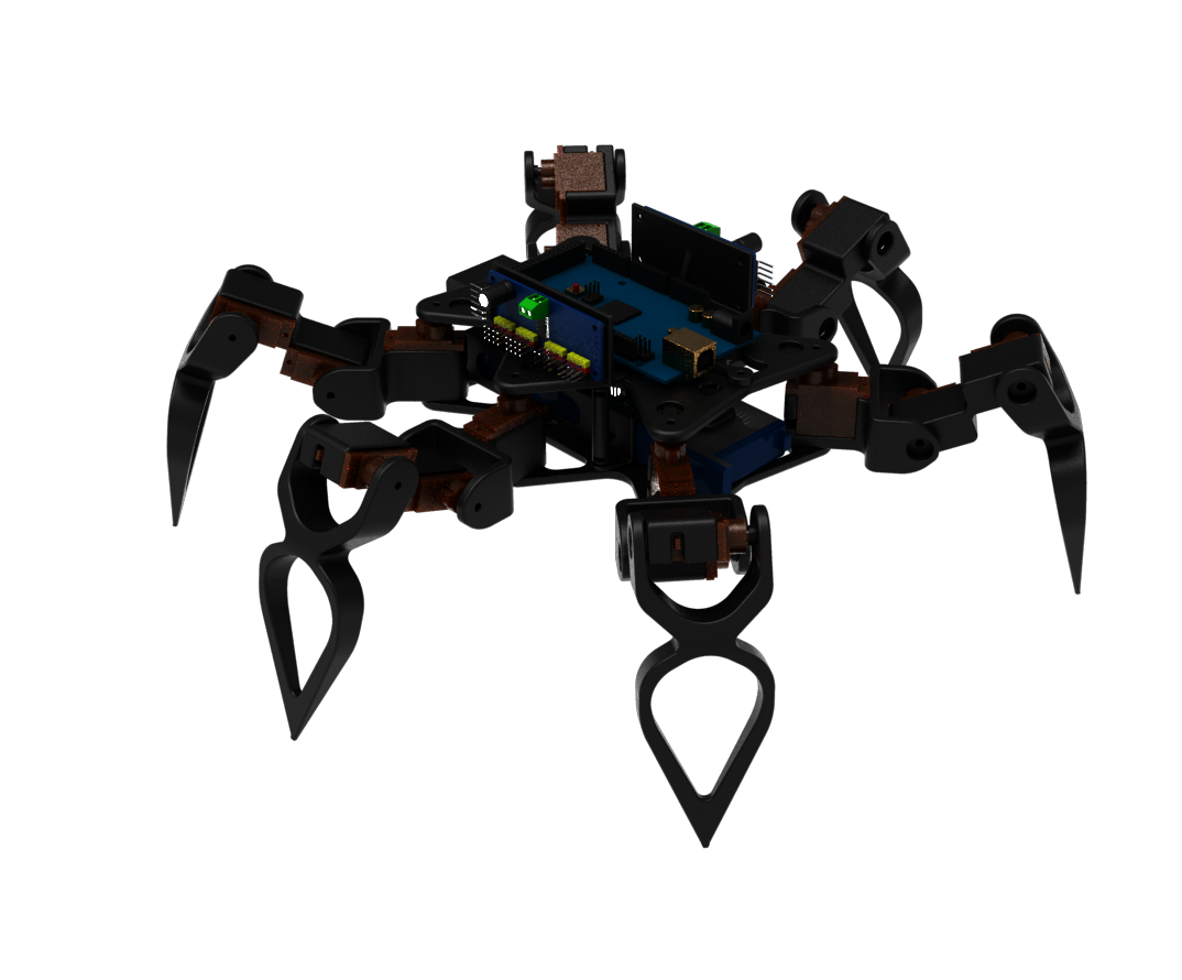
Project Nak was my initial foray into legged robotics. There is a certain beauty in the complexity of many well-coordinated moving parts effecting a single coherent motion; but the appeal of legged robots does not stop at mere aesthetics--they offer agility, adaptivity and dynamism that the ubiquitous wheel cannot parallel.

Legged robots continue to fascinate me, and this will likely not be the last of them you'll see on this site. Stay tuned for more!
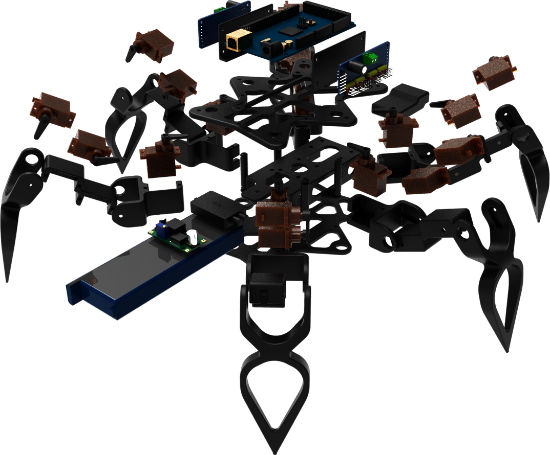

Design Overview

(Click render to toggle exploded view)

All mechanical structures on the Nak are 3D-printed in black PLA. Each leg has 3-DOFs, and each joint is actuated by an MG90 TowerPro servo motor. An Arduino Mega 2560 interfaces with the 18 servo motors through 2 PCA9685 PWM drivers over an I2C bus. Power is supplied through an umbilical cable from a bench power supply, directly powering the Arduino Mega, and through a 12V-to-5V buck converter a 2.4GHz RC receiver module and the 2 PWM drivers.

Initial algorithms were drafted in MATLAB and simulated in VREP. MATLAB was used for its ability to calculate matrix exponents and logarithms, allowing me to employ spatial transforms in Plucker coordinates as a secondary method to check the behaviour of the algorithms. These concepts were subsequently coded into the Arduino.

Read more

Read more


Key Features

Parameterised Gait Trajectory

The parameterisation of the foot trajectory during gaits--as opposed to hard-coding a fixed cyclic sequence--enables the Nak to change its gait speed and direction at any point in its motion instantaneously and elegantly without interruption of the trajectory already in motion. It also accomodates fine-tuning swing-to-stance phase ratios on the fly, allowing the Nak to change how long feet stay in the air or on the ground during gaits to augment gait stability. The parameterisation is compatible with its pose transforms (more on this under Real-time Pose Control), meaning that the Nak can manipulate its body during gaits exactly as it can while stationary.

Foot trajectory is modelled as a spline along which the foot's x-, y- and z- coordinates vary sinusoidally with respect to an incrementing counter, where the rate of increment is controlled by the degree of throttle from the RC controller, and the direction of the trajectory plane by the direction displacement of the throttle. The incrementing counter behaves as a synchronising clock against which the phases of trajectory of every leg is based on, displaced by their respective phase differences, and modified by their respective phase transformations; when the throttle is pushed positive, the legs advance in phase, and when pushed negative, the legs regress in phase, both moving in the direction of throttle displacement while observing their respective phase modifiers.

Read more

Read more

Real-time Pose Control

The Nak is capable of rolling, pitching and yawing; frontal-planar body translations; stance height and leg adduction/abduction adjustments; and 2 variable gaits--a tripod gait and a 6-step ripple gait--of adjustable speed and peak foot-swing height. Each of these manoeuvres are independent, combinable and adjustable in real-time. This is made possible by the usage of volatile variables in the IK algorithm and pin-change interrupts in the control algorithm.

In broad strokes: each foot of the Nak is modelled to be a point on a circle on the ground, so dubbed the stance circle. The motion of the Nak's body is produced by transforming this stance circle accordingly, making a seemingly complex motion easily effected. During gaits, the foot cycles through its trajectory about this point as its origin. As such, the Nak can maintain any transformed posture even during gaits.

Read more

Read more

Passive Muscles

The servos specify a holding torque of 1.8-2.2kg.cm. The Nak weighs in at 0.737kg, with 45mm femurs and 112mm tibiae. During gaits, especially so the tripod gait, the tibia is largely responsible for providing the majority of the locomotive force due to its being the longest segment of each leg. The tibia struggles particularly hard during extension while under load, as most evident from when the Nak strafes laterally during the tripod gait. This is because there is a phase in the gait cycle during which the side opposing the direction of travel of the Nak is supported by only one leg, requiring this solitary limb to provide all the pushing force to move the Nak sidewards.

Passive muscles (in the form of hair-ties) were added across the tibia joints to aid the tibia servo in this. The passive muscle exerts its force in the direction of tibia extension, which the tibia servo easily when counters when unloaded. The contribution of the passive muscle increases with tibia flexion, scaling with the torque demands of the tibia joint.

Read more

Read more


Retrospect and Revision

Leg Design

Shortcomings

Due to the long tibia and short femur and coxa, the workspace of each leg--thinking of each leg as an RRR manipulator chain--is largely dictated by that of the tibia alone about its own joint. The fact that a single DOF dictates the overall reach of each leg greatly limits the effective workspace of all legs combined. In other words, the feet of the Nak are limited to a relatively restricted spatial range despite the long overall length of the leg.

Admittedly, the legs of the Nak were designed to a proportion that looked cool first before being functionally optimal. In my defence, though, this would not have been a problem if the femur and coxa could be made longer. However, in the interests of keeping servo loading minimal, leg segments that are frequently parallel to the ground during loading were intentionally designed to be as short as possible.

Potential Upgrades

Within the constraints of using the same servo motors, the tibia could simply be made shorter. While that would reduce overall leg workspace, the problem here is not the leg's workspace, but the proportion of the leg's workspace a single segment controls. By making the tibia closer to the length of the other 2 segments, the leg will be more efficient in terms of workspace normalised by leg length.

By opting for beefier servo motors however, the femur and coxa can just be made longer, thereby extending both the workspace of the leg, and its workspace efficiency by leg length.

Body Mass

Shortcomings

The body of the Nak is the major contributor to its hefty mass, and had to be that large mostly to accomodate the Arduino Mega 2560. The Arduino Mega 2560 was chosen for its large number of pin-change-interrupt (PCINT) pins necessary for interfacing with the 2.4GHz receiver's 10 channels. However, its large footprint leaves much to be desired.

Potential Upgrades

At the time of writing this, the Teensy 4.0 presents a far superior option to the Arduino Mega 2560. Not only is it a fraction of the size, it boasts a whopping 600MHz in clockspeed (the Arduino Mega 2560 clocks in at only 16MHz!), and 23 digital pins which are all PCINT-enabled! One caveat though: the Teensy 4.0 is exclusively a 3V3 device, with no 5V-tolerant pins, while the 2.4GHz receiver outputs 4-6.5V signals. Yet, this isn't much of a hurdle, considering a very simple and low-cost transistor-transistor-logic (TTL) converter can handle the conversion between 3V3 and 5V signals with ease.

A TTL converter is capable of exchanging signals at frequencies of up to 100MHz to 200MHz, depending on quality of construction. Signals coming from the 2.4GHz receiver are 50Hz in frequency, meaning that the TTL converter will contribute no appreciable rising- and falling-edge hysteresis in the process.