PROJ.
Ramshackle
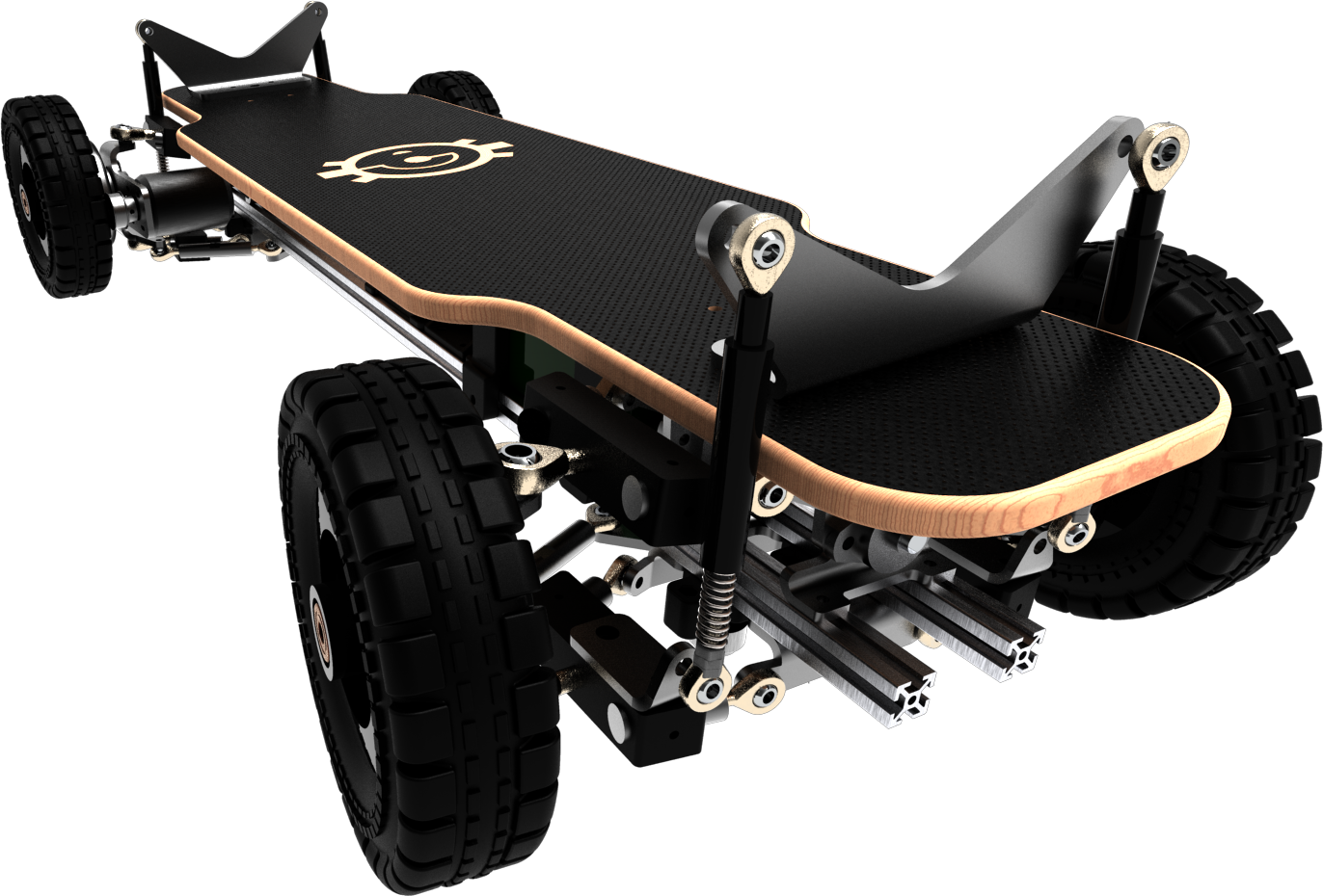
Project Ramschackle draws heavy inspiration from the engineering marvel that is the Baja Board. A true aesthetic treat for the eyes, the Baja Board boasts a masterfully integrated gas-shock system and double-wishbone suspension that are as functional as they are beautiful.
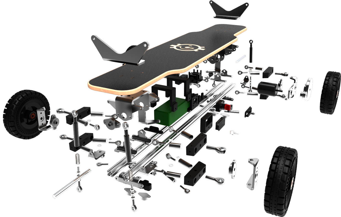
While the Ramshackle can never hope to rival its shining idol, the intangible takeaways from the process of attempting it are the real good stuff. Creating the Ramshackle put me through the full gauntlet of prototyping: from part sourcing and speccing, engineering drawing and GD&T, designing for manufacturing and so much more.
A major regret of mine is not having taken more videos and pictures of this project before I decommissioned it. The media you see on this page don't tell its story all that well, and I apologise for this. Nevertheless, this wild ride truly lived up to its name, both pre- and post-development, and I hope you enjoy it as much as I did!
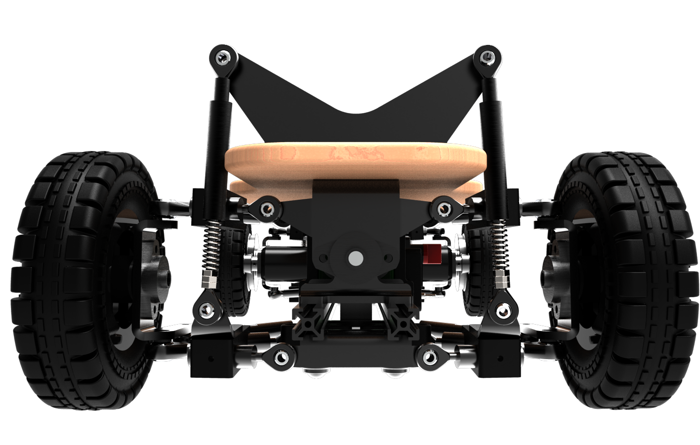
Design Overview
In Action
Key Features
Safety Features
Cost-effective Design
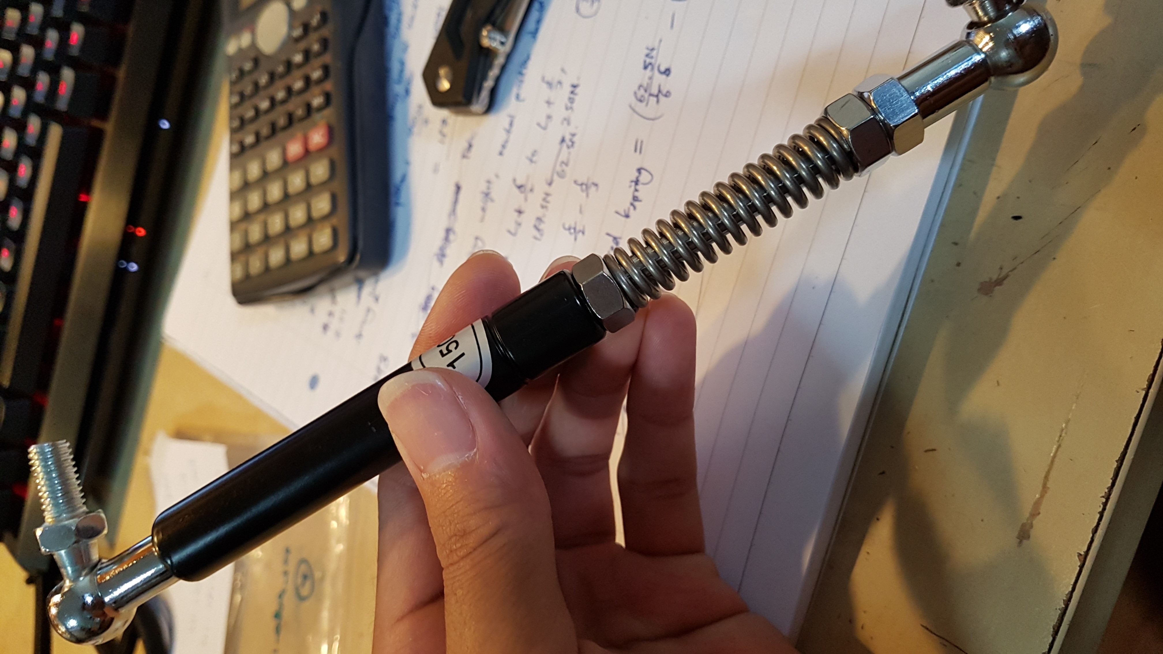
Custom Adjustable Shocks
Ackermann Steering Geometry
Retrospect and Revision
Suspension Control-arm Design
Shortcomings
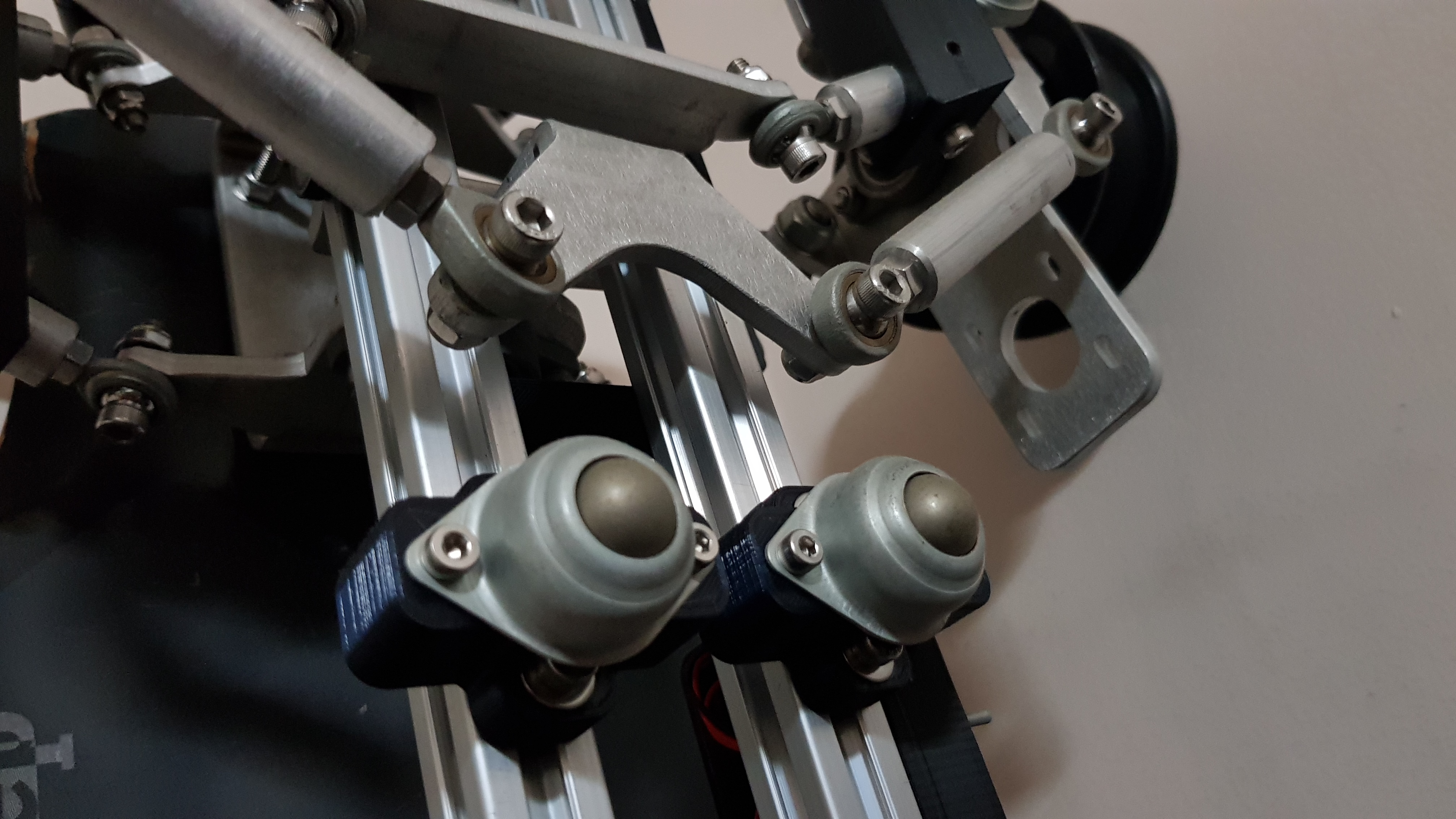
A pretty major caveat of the current control-arm design lies in its impermanent assembly of multiple parts: the two struts on each arm are secured by anemic set-screws to a common block that holds them in the "A" shape at the apex.
During operation, control arms undergo large tensile and compressive forces. In this case, there is a real risk of the set-screws shaking loose and the struts slipping out of the common block completely--a catastrophic failure. If the control arm does not fail by that mode, the stainless steel set-screws shear the softer aluminum surface and allow the rods to slip bit-by-bit over time anyway.
However, it must be said that this design choice was (unfortnately) intentional within my constraints, and for good reasons: 1) Being unable to afford trial-and-error in production, capacity for adjustments and re-assembly was THE top priority; 2) The individual parts of the control arm are collectively very much cheaper to produce; 3) I had a plan-B safety feature designed into it to counter such a failure anyway, and I was willing to take this risk as the only one daring enough to ride this jank.
Potential Upgrades
With a generous budget, it is ideal that the control arm be milled completely out of a single block of raw stock. Not only will that allay the worries of spontaneous unintentional disassembly during operation, the design freedom it presents will allow for an integrated spherical joint within the control arms that interface with the knuckle, which is a more elegant solution to the current bolted rod-end bearing.
However, milling does entail a lot of material wastage, and even with a large budget, it is not very material- nor cost-efficient. A better option--and one that is actually more realistic given my circumstances--is designing it out of weldment members and welding them together. Not only will there be minimal stock wastage, the process of manufacturing a weldment control-arm requires access only to a metal-cutting circular saw, a welding machine (preferably a MIG welder for a newbie such as I) and a working space I can smith freely in without worry about endangering furniture. A weldment control-arm would be the way to go if those were at my disposal, and I do hope that one day they will be.
Going with the weldment option: 5052-H32 square tubes do exist, and material-wise it is easier to weld than 6061-T6, but for structural integrity at the compromise of added weight, carbon steel square tubes would be a better option. In particular, low-carbon steels would be ideal, as high-carbon steels are more prone to weld-cracking and require more pre-heating and post-heating processes to avoid this. The greater strength and stiffness of high-carbon steels is excessive for this purpose anyway.
Wheel Knuckles
Shortcomings
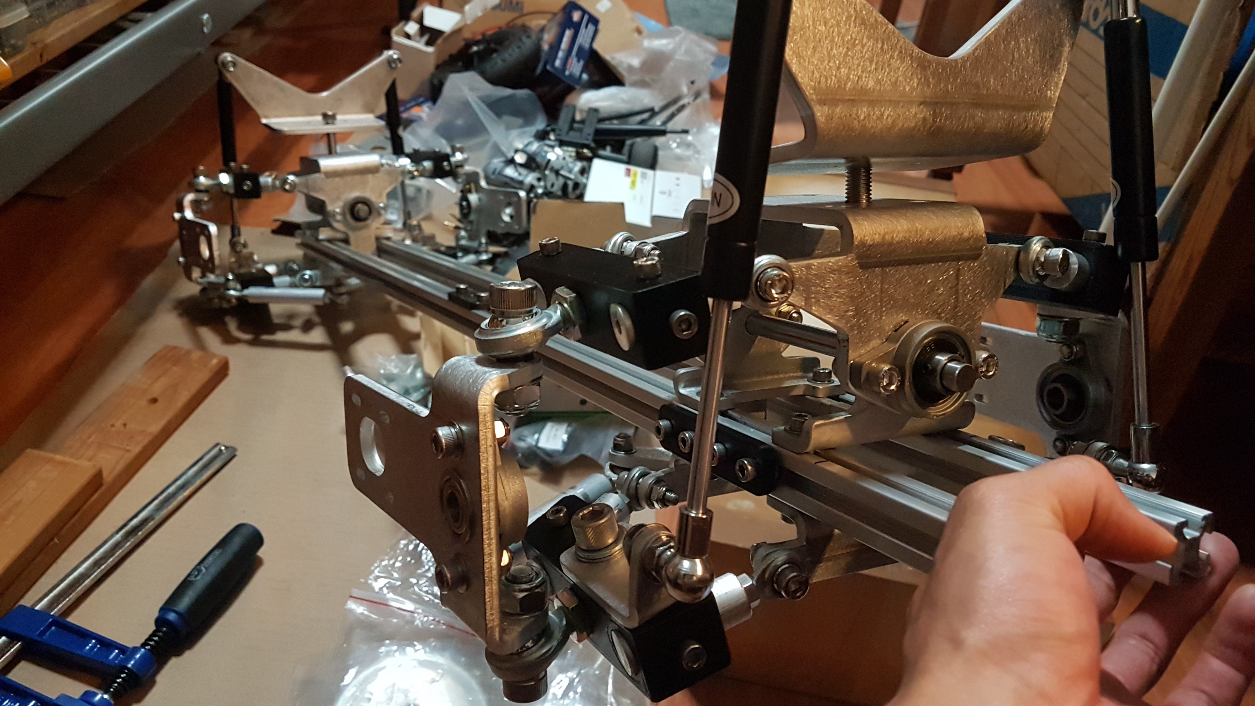
The wheel knuckles, having to be made out of sheet-metal, came with various troublesome design constraints: it is ideal to have the kingpin axis as close to the wheel as possible, but under the sheet-metal design constraint, there was a significant minimal distance the wheel had to be from the knuckle. Consequently, the wheel does not pivot about a vertical axis that is coincident with its plane, increasing wheel scrub and axial forces on the wheel and control-arm assembly.
The wheel axle also experiences larger-than-necessary bending moments due to awkward bearing placements, where the wheel axle extends further than needs to be from the knuckle, and is supported by two admittedly sub-optimal (but budget-wise very agreeable) UCFL bearings on either side of the knuckle. The large bending moments severely increase radial and moment loads on these bearings, decreasing their operational lifespan and hurting performance.
Potential Upgrades
Instead of a clumsy sheet-metal design, a generous budget would accomodate a milled, block-style knuckle. Unlike the control arm, this block-style knuckle can easily be designed for minimal material wastage when milled from raw stock, making milling the ideal method of manufacture for the improved design I'm holding in my mind. In machining this new design, 6061-T6 would be used instead of the current 5052-H32 alloy: 6061-T6 is more machinable than 5052-H32 as it has a higher shear strength (among other factors), making it less "gummy".
This block-style knuckle will present a significantly reduced spatial footprint and would be able to fit snugly up against and inside the rim of the wheel, much closer to the wheel's plane. This would allow the wheel to pivot about a kingpin axis much closer to its wheel plane. Despite a smaller size, it will allow for two in-set bearings spaced further apart along the wheel axle to reduce the radial and moment loads on each bearing. Instead of radial bearings, thrust bearings may be used as well, although that may be a bit excessive for the forces in consideration.